Hotline
+86-136 8495 9862
Email:cennia@szmizhi.com
Add::104,Building 27,Third Industrial Zone, Longxi Community,Longgang District,Shenzhen,China.
Coil Forming & Handling Equipment
Surface Treatment Equipment
Solutions
Application
About Us

Welcome to MIZHI
For consultation/feedback, please call the service hotline: +86-136 8495 9862 Email:cennia@szmizhi.com

Coil Forming & Coil Handling Solutions
Surface Treatment Solutions


Understanding how a floor shot blaster works is essential for appreciating its role in modern surface preparation. These machines have revolutionized the way concrete, steel, and asphalt surfaces are cleaned, profiled, and prepared for coatings or renovations. By propelling abrasive media at high velocity, floor shot blasters efficiently remove contaminants while creating a surface texture that enhances adhesion and durability. This comprehensive exploration delves into the step-by-step operational processes, technical mechanisms, and engineering principles that drive floor shot blasters, shedding light on why they have become indispensable in industries ranging from construction to aerospace.
Chinese manufacturers have played a pivotal role in advancing floor shot blaster technology, integrating smart automation, energy efficiency, and robust design to meet global demands. This guide breaks down the working principles, from abrasive propulsion to dust control, providing a detailed overview for engineers, operators, and industry professionals seeking to master this transformative technology.
(1) The Physics Behind Shot Blasting
At the heart of every floor shot blaster lies the principle of kinetic energy transfer, where abrasive particles become the agents of surface transformation:
Abrasive Acceleration: Centrifugal impellers or pneumatic nozzles accelerate abrasive media to speeds ranging from 60–120 meters per second (m/s). In wheel-type systems, the most common for industrial applications, rotating impellers (2,000–3,500 RPM) use centrifugal force to fling abrasives outward. Nozzle-type systems, relying on compressed air (6–10 bar), offer precision for delicate surfaces.
Impact Mechanics: When abrasive particles strike the floor surface, their kinetic energy is converted into mechanical force that erodes contaminants (paint, rust, oil stains) and textures the substrate. The impact creates micro-craters, increasing surface roughness (30–100 microns for concrete) to enhance adhesive bonding for coatings or overlays.
Surface Interaction Dynamics: The combination of abrasive velocity, particle size, and impact angle determines the treatment outcome. For example, steel grit at 80 m/s effectively removes thick epoxy coatings from concrete, while fine steel shot at 60 m/s gently peens steel surfaces to improve fatigue resistance.
(2) The Three Stages of Floor Shot Blasting
1. Contaminant Removal: Abrasives shear off rust, paint, and scale through mechanical erosion. The high-velocity impact breaks down bonds between contaminants and the substrate, allowing their removal.
2. Surface Profiling: The continuous bombardment of abrasives creates a uniform roughness profile. For concrete, this profile (measured by ICRI CSP standards) is critical for coating adhesion; for steel, it achieves cleanliness standards like ISO 8501-1 Sa (5).
3. Mechanical Enhancement (Optional): In applications like steel peening, the impact induces compressive stresses in the surface layer, counteracting tensile stresses that cause fatigue failure.
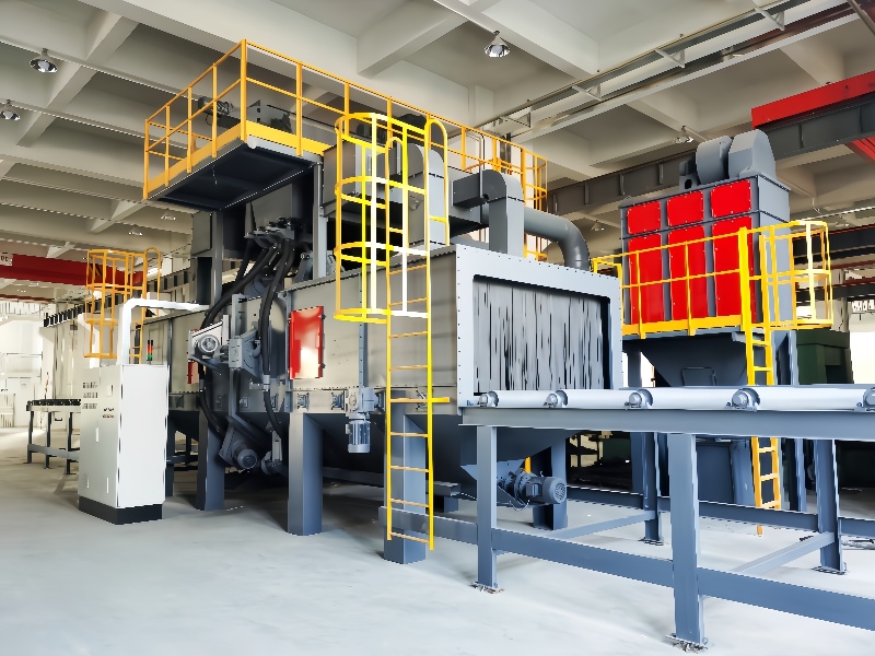
The Blasting Module: Heart of the Operation
(1).1 Impeller Systems (Wheel-Type Blasters)
Design and Function:
Multi-blade centrifugal impellers (8–16 blades) are driven by 15–75kW electric motors, with backward-curved blades optimizing abrasive velocity while minimizing wear.
Rotational speed (2,000–3,500 RPM) determines blasting intensity. Higher speeds (e.g., 3,000 RPM) are ideal for aggressive cleaning, while lower speeds (2,000 RPM) suit delicate surfaces.
Abrasive Feeding Mechanism:
Abrasive media is fed into the impeller’s center via a hopper, accelerated by centrifugal force, and ejected through the blades at high velocity.
Hydraulic or pneumatic valves regulate media flow, with sensors ensuring consistent supply. Advanced models use AI algorithms to adjust feed rates based on surface condition.
2 Nozzle Systems (Pressure-Type Blasters)
Design and Function:
Tungsten carbide nozzles (8–15mm diameter) use compressed air (6–8 bar) to accelerate abrasives. Nozzle manifolds may be robotically positioned for complex contours.
Ideal for precision applications (e.g., removing paint from intricate steel structures) or small areas where mobility is limited.
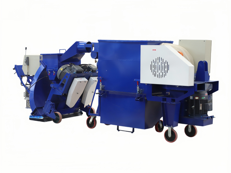
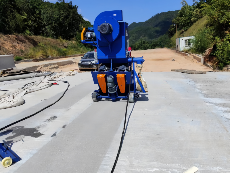
(2) Mobile Chassis and Propulsion
Walk-Behind Models: Compact units (200–500kg) with manual steering, suitable for small areas (50–200 m²/h). Electric drives ensure quiet operation indoors.
Ride-On Models: Larger machines (1,000–3,000kg) with diesel or electric drives for high productivity (500–2,000 m²/h). Hydraulic steering and enclosed cabs enhance operator comfort.
Tracked Vehicles: For rough terrain, offering superior traction on uneven surfaces like bridge decks. Ideal for outdoor projects in challenging environments.
(3) Abrasive Recycling System
A closed-loop recycling system maximizes efficiency and reduces operational costs:
1. Collection: Used abrasive and debris fall into a hopper beneath the blasting chamber, vacuumed by negative pressure.
2. Elevation: Screw conveyors or bucket elevators transport media to a cyclonic separator.
3. Separation: The separator uses centrifugal force to remove dust, fines, and debris. Clean abrasive is directed to the storage hopper, while waste is discharged.
4. Media Storage: Clean abrasive is stored in hoppers, ready to be fed back into the impellers or nozzles.
(4) Dust Control System
Critical for safety and environmental compliance:
Cyclone Pre-Filter: Removes large debris before fine particles enter the main filter, extending its lifespan.
HEPA Filters: Capture 99.97% of particles >0.3 microns, meeting strict indoor air quality standards (e.g., OSHA 29 CFR 19(1)000).
Wet Scrubbers: For outdoor use, combining water and abrasives to suppress dust in arid climates. Negative pressure chambers prevent dust escape, with pressure gauges monitoring filter clogging in real-time.
(1) Pre-Operation Setup
1. Surface Assessment: Identify substrate type (concrete, steel, asphalt) and contamination level (rust, paint, oil).
2. Abrasive Selection:
Concrete: Steel grit (G25–G50) for aggressive cleaning; steel shot (S330–S460) for light profiling.
Steel: Coarse steel grit (G25) for rust removal; fine shot (S110–S170) for peening.
Asphalt: Medium steel shot (S330) to remove rubber without damaging the surface.
3. Machine Configuration:
Adjust blasting width (500–2,000mm) via modular impeller setups.
Set impeller speed (RPM) and travel speed (5–15 km/h) based on surface hardness and contamination severity.
(2) Blasting Operation
1. Abrasive Propulsion:
Impellers fling abrasives onto the surface, with the machine moving forward at a consistent speed.
The rotating impeller creates a circular blast pattern, overlapping each pass by 10–20% to ensure uniform coverage.
2. Surface Treatment:
Abrasives remove contaminants and create a roughened profile. For example, blasting concrete with G40 grit at 10 km/h produces an ICRI CSP 4 profile (50–75 microns).
Steel surfaces are cleaned to Sa (5) (near-white metal), with visible metal shine and minimal staining.
(3) Abrasive Recycling in Real-Time
1. Collection Phase: Used abrasive and debris are suctioned into the hopper via a powerful vacuum system.
2. Separation Phase: In the cyclonic separator, centrifugal force throws heavy abrasive particles to the walls, while light dust and fines are drawn into the filter system.
3. Recycling Phase: Clean abrasive falls into the storage hopper, while dust is trapped in filters. The recycled abrasive is fed back into the impellers, reducing consumption by 50–70%.
(4) Dust Management During Operation
Negative Pressure System: The blasting chamber maintains negative pressure to prevent dust escape, with air flowing from clean areas to the chamber.
Filter Cleaning: Pneumatic pulse systems periodically clean HEPA filters, dislodging dust and maintaining suction efficiency.
Emission Control: Monitors ensure dust levels remain within regulatory limits (e.g., <50 mg/m³ for indoor operations).
Operational Parameters and Their Impact
(1) Abrasive Properties
Particle Shape:
Spherical shot: Gentle cleaning, peening (e.g., steel floors).
Angular grit: Aggressive cleaning, profiling (e.g., concrete coatings).
Particle Size:
Coarse (e.g., G25 grit): Deeper profiles, faster material removal.
Fine (e.g., S110 shot): Shallow profiles, delicate surfaces.
Hardness:
High-hardness abrasives (60–65 HRC): Durable, ideal for tough contaminants.
Low-hardness abrasives (40–45 HRC): Less aggressive, suitable for soft substrates.
(2) Machine Settings
Impeller Speed: Directly affects abrasive velocity. Higher speeds (3,500 RPM) for heavy rust; lower speeds (2,000 RPM) for light cleaning.
Travel Speed: Faster speeds (15 km/h) for large areas with minimal contamination; slower speeds (5 km/h) for thick coatings.
Blasting Distance: Optimal distance (100–300mm) ensures consistent abrasive impact. Laser height sensors maintain this distance automatically in advanced models.
(3) Environmental Factors
Humidity: High humidity can cause steel surfaces to re-rust quickly post-blasting. Apply coatings within 4 hours in humid conditions.
Temperature: Freezing temperatures can affect abrasive flow; heated hoppers may be required in cold climates.
(1) Automation and Control Systems
PLC Core: Siemens, Mitsubishi, or domestic PLCs manage process parameters, interlocks, and diagnostics. Touchscreen HMIs display real-time data (impeller speed, filter pressure, abrasive level).
Recipe Management: Store pre-set programs for different surface types (e.g., concrete vs. steel), ensuring consistent results and reducing operator error.
Laser Guidance: Maintains straight travel paths and precise overlap, critical for large projects like airport runways.
(2) IoT and Smart Monitoring
Remote Diagnostics: Cloud-based platforms allow real-time tracking of machine status, maintenance needs, and productivity metrics. Alerts notify operators of filter clogs or low abrasive levels.
Predictive Maintenance: Sensors on impellers, motors, and filters detect wear and temperature anomalies, scheduling maintenance before failures occur.
Data Analytics: Machine learning algorithms analyze production data to optimize cycle times, energy use, and component lifespans.
Safety and Environmental Considerations
(1) Operational Safety Mechanisms
Emergency Stops: Instantly halt all machine functions in case of malfunctions or accidents.
Interlocked Doors: Prevent blasting when chamber doors are open, protecting operators from abrasive exposure.
Overload Protection: Shuts down motors if excessive loads are detected, preventing damage to components.
(2) Environmental Compliance
Dust Emission Standards:
Indoor: Meets GB 16297-1996 (<50 mg/m³) and OSHA 29 CFR 19(1)000.
Outdoor: Wet dust suppression systems reduce emissions below local environmental limits.
Noise Control: GB 12348-2008 mandates <85 dB(A) at operator positions. Electric models often achieve <75 dB for urban use.
Waste Management: Recycled abrasive reduces landfill waste, while eco-friendly media (glass beads, walnut shells) minimizes environmental impact.
Common Applications and Customization
(1) Concrete Floor Renovation
Process Example: Blasting a warehouse floor with G40 steel grit at 8 km/h removes 20-year-old epoxy coatings, achieving a CSP 4 profile for new polyurea application.
Key Parameters: Impeller speed 2,800 RPM, blasting width 1.2m, abrasive flow 15 kg/m².
(2) Steel Structure Maintenance
Process Example: Shot peening a ship deck with S330 steel shot at 3,000 RPM induces compressive stresses, improving fatigue life. Cleanliness reaches Sa (5).
Key Parameters: Travel speed 6 km/h, blasting distance 200mm, overlap 15%.
(3) Airport Runway Treatment
Process Example: Blasting a concrete runway with G50 grit at 12 km/h restores skid resistance, achieving ICRI CSP 5.
Key Parameters: Dual impellers, blasting width 2m, GPS-guided navigation for uniform coverage.
9. Maintenance to Ensure Optimal Functionality
(1) Routine Maintenance Schedule
Daily:
Check abrasive level and replace contaminated media.
Clean or shake out dust filters.
Lubricate chains and bearings; check for loose bolts.
Weekly:
Inspect impeller blades for wear (replace if thickness reduces by 30%).
Test dust collector efficiency with a particle counter.
Check tire pressure and drive system functionality.
Monthly:
Replace worn chamber linings and blasting hoses.
Service hydraulic/pneumatic systems.
Calibrate laser height sensors and pressure gauges.
| Problem | Cause | Solution |
|---|---|---|
| Inconsistent profile | Uneven speed or abrasive flow | Adjust VFD settings; clear conveyor blockages |
| Excessive dust | Clogged filters or faulty seals | Replace filters; inspect chamber seals |
| Reduced efficiency | Worn impeller blades or low abrasive flow | Replace blades; clean feed valves |
| Machine vibration | Unbalanced impeller or loose components | Balance impeller; tighten fasteners |
Future Innovations in Floor Shot Blaster Technology
(1) Autonomous Operation
Driverless Systems: AI-powered blasters with LiDAR and GPS for autonomous operation, ideal for large, repetitive projects like runway maintenance.
5G Connectivity: Remote operation from safety zones, critical for hazardous environments like chemical plants.
(2) Sustainable Technologies
Electric Propulsion: Battery-powered blasters reduce carbon emissions by 80%, with solar-charging trailers for remote sites.
Closed-Loop Recycling: Advanced separators achieve 99% media reuse, minimizing waste and costs.
Eco-Abrasives: Wider adoption of recycled steel grit, crushed glass, and agricultural by-products.
(3) Advanced Materials
Composite Wear Components: Lightweight, high-strength composites for impeller blades and chamber linings, extending lifespan by 2–3 times.
Nano-Coated Surfaces: Anti-wear coatings for critical components, reducing maintenance needs.
A floor shot blaster operates at the intersection of physics, engineering, and materials science, transforming surfaces through the precise application of kinetic energy. From abrasive propulsion to dust control, each component and process is designed to deliver optimal surface preparation efficiently and sustainably. As Chinese manufacturers continue to integrate smart technologies and eco-friendly innovations, floor shot blasters will only become more capable, reliable, and essential to industries worldwide. For anyone involved in surface treatment, understanding how these machines work is key to harnessing their full potential and achieving exceptional results in any project.
sign up newsletter
Email:cennia@szmizhi.com
Add::104,Building 27,Third Industrial Zone, Longxi Community,Longgang District,Shenzhen,China.