Hotline
+86-136 8495 9862
Email:cennia@szmizhi.com
Add::104,Building 27,Third Industrial Zone, Longxi Community,Longgang District,Shenzhen,China.
Coil Forming & Handling Equipment
Surface Treatment Equipment
Solutions
Application
About Us

Welcome to MIZHI
For consultation/feedback, please call the service hotline: +86-136 8495 9862 Email:cennia@szmizhi.com

Coil Forming & Coil Handling Solutions
Surface Treatment Solutions


A shot peening machine system is a complex integration of mechanical, electrical, and material processing components designed to induce compressive residual stresses on workpiece surfaces. Unlike standalone machines, these systems emphasize modularity, automation, and process consistency across industrial scales. The technology traces its roots to post-WWII aerospace needs, evolving from manual blasting to fully automated production lines that handle millions of parts annually.
Key System Design Principles:
Holistic Process Control: Systems coordinate shot propulsion, workpiece handling, media management, and quality assurance to achieve repeatable stress profiles. For example, a Boeing 787 fuselage panel system must maintain ±3% stress variation across 10,000+ parts.
Scalability and Flexibility: Modular components allow system reconfiguration for different materials (aluminum, titanium, composites) and part sizes (from 1 mm screws to 10 m aircraft wings).
Industry 4.0 Integration: IoT sensors, cloud computing, and AI algorithms enable real-time monitoring and predictive maintenance. A 2023 study by McKinsey found smart shot peening systems reduce unplanned downtime by 45%.
System Evolution Milestones:
1. 1950s–1970s: Pneumatic batch systems with manual loading, limited to simple geometries.
2. 1980s–2000s: Computer-controlled centrifugal systems with conveyor belts, e.g., General Motors’ engine block peening lines.
3. 2010s–present: Fully automated robotic systems with AI-driven quality control, such as Airbus’ A350 wing component systems.
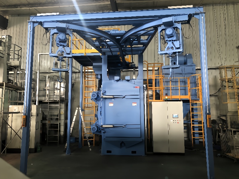
Shot peening machine systems comprise interdependent subsystems that work in concert to deliver precise surface treatment. Each subsystem is optimized for reliability, efficiency, and seamless coordination.
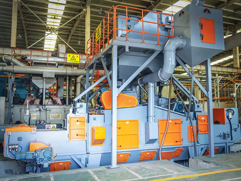
1 Shot Propulsion and Media Management System
Propulsion Technology Integration:
Pneumatic-Centrifugal Hybrid Systems: Combine airblast nozzles (for precision) and centrifugal wheels (for throughput). A BMW engine plant uses this hybrid setup, peening crankshafts with 0.8 mm steel shots at 65 m/s via centrifugal wheels, then refining details with pneumatic nozzles.
Adaptive Velocity Control: Servo valves and variable frequency drives (VFDs) adjust shot velocity in real-time. For titanium components, the system may reduce velocity from 80 m/s to 60 m/s mid-process to avoid surface damage.
Intelligent Media Handling:
Closed-Loop Recycling Networks: Cyclone separators (efficiency 99.5% @ 50 μm), magnetic filters, and vibratory screens maintain shot purity. A Tesla EV motor system recycles 98% of steel shots, reducing media costs by $100,000/year.
Auto-Change Media Modules: Robotic arms swap hoppers (steel, glass, ceramic) based on part recipes, enabling multi-material processing in a single system.
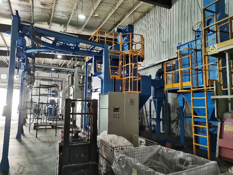
2 Workpiece Handling and Automation System
High-Speed Conveyor Networks:
Modular Conveyor Systems: Servo-driven belts (speed 0.1–2 m/s) with quick-release fixtures accommodate part variations. An Airbus system processes 200 wing spars/day with ±1 mm positioning accuracy.
Palletizing Robotics: 6-axis robots (e.g., FANUC R-2000iB) load/unload parts from conveyor to peening cells, reducing manual labor by 80%.
Complex Geometry Management:
5-Axis Positioning Stations: Turntables and tilters enable 360° access to components like turbine blades. The MTU Aero Engines system uses 5-axis fixtures to peen all airfoil surfaces in one setup.
3 Control and Monitoring Ecosystem
Industrial PLC and SCADA Integration:
Programmable Logic Controllers: Siemens S7-1500 PLCs coordinate shot flow (5–20 kg/min), air pressure (2–8 bar), and robot motion, with cycle time precision of ±50 ms.
Supervisory Control and Data Acquisition (SCADA): Software like Wonderware InTouch visualizes real-time data (shot velocity, coverage, stress) on HMIs, generating trend reports for process optimization.
AI-Powered Process Control:
Machine Learning Predictive Models: Neural networks analyze historical data to predict stress distribution. A 2024 case study by GE Aviation showed AI reduced trial peening runs for new engine parts from 30 to 5.
4 Safety and Environmental Subsystem
Industrial Safety Networks:
Safety PLCs: TÜV-certified safety controllers (e.g., Pilz PSS 4000) monitor interlocks, emergency stops, and dust levels, with response times <100 ms.
Environmental Compliance Systems:
Industrial Dust Collection: Baghouse filters (efficiency 99.9% @ 1 μm) and HEPA after-filters maintain air quality below 0.5 mg/m³. A Boeing facility reduced particulate emissions by 95% using this setup.
Designing a shot peening machine system requires balancing technical requirements, production goals, and lifecycle costs. This section dissects critical design phases and trade-offs.
1 System Requirements Analysis
Process Intensity vs. Throughput:
High-Intensity Systems: For aerospace components, systems may prioritize stress depth (0.5–1 mm) over speed, using large steel shots (1–1.5 mm) at 80 m/s.
High-Throughput Systems: Automotive lines process 1000+ parts/hour with smaller shots (0.5 mm) and lower velocities (50 m/s), sacrificing some depth for productivity.
Material Compatibility Matrix:
Aluminum Alloys: Require gentle peening (glass beads, 0.1–0.5 mm, 30–50 m/s) to avoid surface degradation.
High-Strength Steels: Demand robust systems (tungsten carbide shots, 0.8 mm, 70–90 m/s) to induce deep compressive stresses (-800 to -1000 MPa).
2 Modular System Design Principles
Plug-and-Play Subsystem Integration:
Standardized Interfaces: Mechanical (ISO robot mounts), electrical (M12 connectors), and communication (OPC UA) standards allow quick subsystem swaps. A Volkswagen plant reconfigured its peening system for a new EV motor in 48 hours using modular components.
Scalability Planning:
Parallel Processing Nodes: Systems can add extra peening cells (e.g., from 2 to 4) to double throughput, with shared media and control systems. This reduces expansion costs by 30% vs. building a new system.
3 Reliability Engineering and Redundancy
Mean Time Between Failures (MTBF) Optimization:
Critical Component Redundancy: Dual-shot hoppers, backup compressors, and redundant PLCs ensure MTBF >50,000 hours. A Rolls-Royce system achieved 99.8% availability over 3 years using this approach.
Predictive Maintenance Integration:
Vibration Analysis: Accelerometers on motors and pumps detect bearing wear, triggering maintenance alerts before failure. This reduces unplanned downtime by 70%.
Technical Deep Dive: In-Line vs. Robotic Cell Systems
Throughput vs. Flexibility:
In-line systems excel in high-volume, simple parts (e.g., automotive springs), processing 2000 parts/hour with 99% consistency.
Robotic cells shine in complex geometries (turbine blades), though throughput is lower (500 parts/hour) due to intricate path planning.
Cost-Benefit Analysis:
In-line systems cost $1–3M, with ROI in 1–2 years for high-volume production.
Robotic cells cost $5–10M, but reduce rework from 15% to 2% in aerospace, yielding ROI in 3–4 years.
Shot peening systems underpin reliability in critical industries, with integrated solutions tailored to mass production or precision engineering.
1 Aerospace and Defense Systems
Turbine Engine Production Lines:
Integrated Blade Processing Systems: Fanuc robots peen turbine blades with 0.3 mm ceramic shots at 70 m/s, followed by automated XRD stress mapping. GE’s LEAP engine system processes 500 blades/day, with stress uniformity ±5%.
Structural Component Systems: Automated cells peen fuselage frames with 0.1 mm glass beads, preventing fatigue cracks. Airbus’ A320neo system reduces maintenance costs by $20M/year.
Defense Applications:
Military Aircraft Retrofit Systems: Mobile containerized systems peen helicopter rotor blades in field conditions, enabling rapid repairs during deployments. The US Army’s Portable Peening System (P2S) can be airlifted to forward bases.
2 Automotive and EV Manufacturing
Powertrain Integration Systems:
Engine Block Peening Lines: In-line systems peen cylinder bores with 0.6 mm cast iron shots at 60 m/s, improving wear resistance. A Toyota plant processes 1000 engine blocks/day, extending service life from 200,000 to 300,000 miles.
EV Motor Component Systems: Robotic cells peen electric motor shafts with 0.2 mm ceramic shots, reducing stress concentrations in splines. Tesla’s Model Y system achieves 4 Nm/kg torque density, critical for range optimization.
Suspension System Production:
Leaf Spring Conveyor Systems: High-speed lines peen springs with 1 mm steel shots at 70 m/s, increasing fatigue life from 10^5 to 10^6 cycles. Magna’s system produces 5000 springs/day for OEMs.
3 Medical Device and Biomedical Systems
Implant Manufacturing Systems:
Cleanroom-Integrated Robotic Cells: ISO Class 5 compliant systems peen titanium implants with 0.05 mm glass beads, creating rough surfaces (Ra 2–3 μm) for osseointegration. Stryker’s system achieves 99.9% sterility, with 30% faster bone growth in clinical trials.
Micro-Component Systems:
High-Precision Tabletop Systems: Miniature robotic arms peen stents with 10 μm plastic shots, improving fatigue life in cyclic blood flow (10^8 cycles). Medtronic uses this for 99.97% yield in stent production.
4 Renewable Energy and Heavy Industry
Wind Turbine Component Systems:
Gearbox Peening Lines: Automated systems peen planetary gears with 1.2 mm steel shots at 80 m/s, combating torsional fatigue. Siemens Gamesa’s system reduces gearbox failures by 75%, lowering O&M costs by $1M/year per wind farm.
Offshore Oil and Gas Systems:
Subsea Component Systems: Corrosion-resistant systems peen valves with tungsten carbide shots, extending life from 5 to 15 years in saltwater. BP’s offshore system operates at 1000 m depth, with remote monitoring via ROV.
System Calibration, Quality Control, and Process Validation
Shot peening machine systems require rigorous validation to ensure repeatable performance and compliance with industry standards.
1 System-Level Calibration Protocols
Multi-Point Velocity Mapping:
Laser Doppler Anemometry (LDA): Scans the entire shot stream (width 100–500 mm) to ensure velocity uniformity (±3%). For a centrifugal wheel system, LDA confirms 80 m/s velocity within ±2.4 m/s across the stream.
Almen Strip System Validation:
Automated Almen Testing Stations: Robotic arms position Almen strips in the work envelope, measuring deflection (N, A, C scale) with micrometer accuracy. A system producing aerospace parts must achieve 0.015A intensity with ±0.002A variation.
2 Integrated Quality Management Systems (QMS)
Data-Driven Process Control:
Manufacturing Execution Systems (MES): Software like Siemens Opcenter integrates peening data with ERP, tracking every part’s stress profile from raw material to assembly. Boeing’s MES logs 10,000+ parameters per part for traceability.
Non-Destructive Testing Integration:
Automated XRD Scanners: Robotic arms equipped with XRD sensors map residual stress (spatial resolution 0.5 mm) across large components. A jet engine disk system completes full stress mapping in 2 hours, vs. 8 hours manually.
3 System Validation and Compliance
Industry Standard Compliance:
SAE AMS 2432 Certification: Systems must pass 50+ validation tests, including shot cleanliness, velocity stability, and coverage. A system certified for AMS 2432 can process parts for Boeing, Airbus, and NASA.
Process Capability Studies (Cpk):
Long-Term Performance Monitoring: Collecting 300+ data points over 30 days to ensure Cpk >1.33 for key parameters (stress depth, intensity). A automotive system achieved Cpk 1.67 for shot velocity, exceeding OEM requirements.
Challenges, Innovations, and Future Trends in Shot Peening Systems
Shot peening machine systems face technical and operational challenges, driving innovation in automation, sustainability, and integration.
1 Technical Challenges and Solutions
Multi-Material Process Integration:
Challenge: Peening dissimilar materials (e.g., aluminum and steel in a single assembly) risks cross-contamination and parameter conflicts.
Solution: Segmented processing cells with airtight barriers and automated media changers. A SpaceX rocket engine system uses this to peen titanium and Inconel components without cross-contamination.
Energy Consumption in High-Volume Systems:
Challenge: Centrifugal systems consume 10–20 kW/h, contributing to high utility costs.
Solution: Regenerative drives and variable speed controls reduce energy use by 30%. A BMW system cut annual energy costs from $120,000 to $84,000 using this approach.
2 Sustainability and Circular Economy Innovations
Closed-Loop Media Recycling:
Advanced Shot Refinement: Plasma treatment regenerates worn shots, extending media life from 50 to 200 cycles. A 2024 pilot by Rösler reduced steel shot consumption by 75%, with 90% lower waste.
Green Energy Integration:
Solar-Powered Mobile Systems: Containerized peening systems with integrated solar arrays (10 kW) and battery storage, suitable for off-grid locations. Vestas deployed this for wind farm maintenance in remote areas, reducing diesel use by 10,000 L/year.
3 Future Trends in System Design
Digital Twin-Driven Systems:
Virtual Commissioning: Full-system digital twins (robots, conveyors, shot flow) allow 90% of programming to happen in simulation. A 2025 concept by Airbus reduced physical commissioning from 8 weeks to 1 week using twins.
Hybrid Manufacturing Systems:
3D Printing and Peening Integration: Systems that print components and peen them in-situ, reducing stress in additive manufacturing. SLM Solutions’ new system improves Inconel 718 fatigue life by 40% through hybrid processing.
AI-Driven Autonomous Systems:
Self-Optimizing Peening: Neural networks continuously adjust parameters based on real-time stress data. A 2026 prototype by GE Research achieved 95% first-pass quality, eliminating manual adjustments.
sign up newsletter
Email:cennia@szmizhi.com
Add::104,Building 27,Third Industrial Zone, Longxi Community,Longgang District,Shenzhen,China.