Hotline
+86-136 8495 9862
Email:cennia@szmizhi.com
Add::104,Building 27,Third Industrial Zone, Longxi Community,Longgang District,Shenzhen,China.
Coil Forming & Handling Equipment
Surface Treatment Equipment
Solutions
Application
About Us

Welcome to MIZHI
For consultation/feedback, please call the service hotline: +86-136 8495 9862 Email:cennia@szmizhi.com

Coil Forming & Coil Handling Solutions
Surface Treatment Solutions


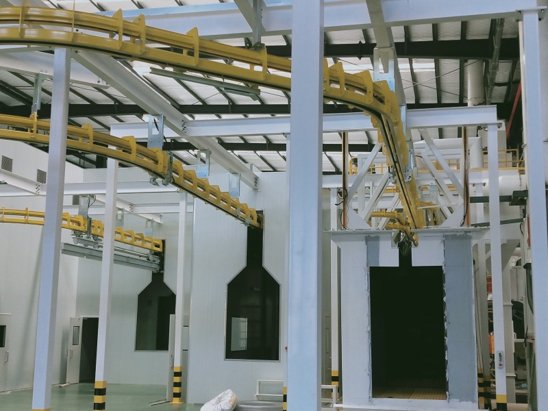
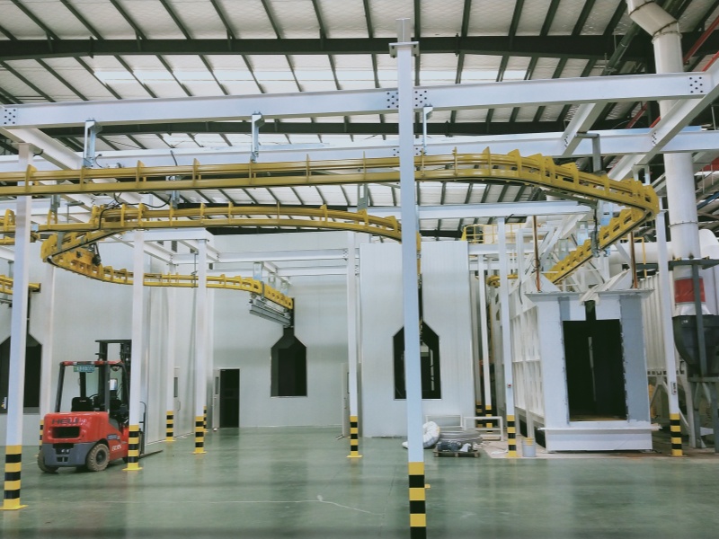
1.Name:Shot Blasting +Powder Coating Line
2.Workpiece: L2100*W300*H1300mm
3.Line speed:1-3m/min
A shot blasting and powder coating line is a kind of industrial production line widely used in the metal processing and manufacturing industries.
Work Principle
1.Shot Blasting Stage: In this stage, small steel shot or other abrasives are propelled at high speed by a blasting machine onto the surface of the workpiece. The kinetic energy of the shot when it impacts the surface removes impurities such as rust, mill scale, and old paint. This process also creates a rough surface profile, which is beneficial for the subsequent powder coating adhesion. For example, when processing automotive parts, shot blasting can effectively remove rust from the surface of the parts and create a suitable roughness to improve the bonding of the coating.
2.Powder Coating Stage: After the workpiece surface has been cleaned and roughened by shot blasting, it enters the powder coating area. In this process, powder coating material, which is usually a mixture of resin, pigment, filler, and additives, is applied to the workpiece surface using electrostatic spray methods. The powder particles become charged in the spray gun and are attracted to the surface of the workpiece under the action of the electric field, forming a uniform powder coating. Then, the workpiece enters a curing oven, where the powder coating is melted, flows out, and forms a continuous and smooth coating through chemical and physical reactions at high temperatures.
")
(1)Powder coating process flow parameters:
NO. | Name | Process Method | Temperature | Time | Remarks |
1 | Loading | Manual | |||
2 | Shot blasting | Shot Blasting Machine | |||
3 | Wash with hot water | Spray | 45-50℃ | 30S | Plate heating outside the tank, equipped with a complete tank liquid monitoring system |
4 | Pre-degreasing | Spray | 45-50℃ | 60S | |
5 | Main degreasing | Spray | 45-50℃ | 120S | Plate heating outside the tank, equipped with a complete tank solution monitoring system, overflows to pre-degreasing |
6 | Water-washed 1# | Spray | Room temperature | 36S | Overflow drainage ditch |
7 | Water-washed 2# | Spray | Room temperature | 36S | Overflow into water washing 1 |
8 | Fresh water is sprayed directly | Spray | Room temperature | Single row | Flow into the water wash 2 |
9 | Surface conditioning | Spray | Room temperature | 60S | Overflow drainage ditch |
10 | Phosphating | Spray | 35-45℃ | 180S | The external plate heat exchanger is equipped with a complete tank liquid monitoring system |
11 | Fresh pure water sprayed directly | Spray | Room temperature | Single row | |
12 | Water-washed 3# | Spray | Room temperature | 30S | Overflow drainage ditch |
13 | Water-washed 4# | Spray | Room temperature | 30S | Overflow into the water washing 3 |
14 | Pure water-washed 1 | Spray | Room temperature | 30S | Overflow into the water washing 4 |
15 | Fresh pure water sprayed directly | Spray | Room temperature | Single row | Flow into pure water 1 |
16 | Dripping water + blowing water | Automatic | Room temperature | 7min | Reserve manual water blowing before entering the drying furnace |
17 | Moisture drying furnace | Hot air circulation | 120-16o℃ | 15min | Direct heating of natural gas |
18 | Natural cooling | R.T | 12min | ||
19 | Powder spraying | Reciprocating machine + hand supplement | R.T | Large cyclone quick color change, automatic gun + reserved manual re-spray position | |
20 | Powder curing furnace | Hot air circulation | 180-220°C | 30min | Direct heating of natural gas,Adjustable temperature |
21 | Natural cooling | R.T | 17min | ||
22 | Unloading | Manual | R.T |
(2)Process Description
① In the process design, the rust removal process for going online is not taken into account, and the rust is resolved before going online.
② Pre-degreasing, main degreasing and ceramizing adopt medium-temperature processes. The heating method is indirect heating outside the hot water tank, and the secondary heating time is less than 45 minutes.
③ To save water, all water washing processes adopt multi-stage counter-flow technology. Among them, the pre-degreasing, degreasing and ceramizing tanks are equipped with mixed-flow stirring tubes to prevent the sedimentation of the tank solution.
④ Powder coating adopts an automatic electrostatic spraying process to enhance the powder coating rate.
⑤ The powder spraying adopts a large cyclone two-stage recovery system, with automatic spraying by a reciprocating machine, and powder is sprayed on both sides and the front.
3.Equipment composition and performance description
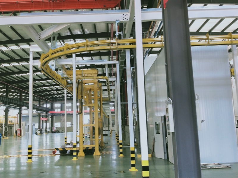
(1) Coating line: The production line adopts the QXT-300.100 chain conveyor production line, mainly consisting of the following parts: shot blasting machine, pretreatment section, powder spraying section, moisture drying section, powder curing section, conveying system, and auxiliary equipment of the production line.
(2) Pretreatment section: A 10-station cleaning machine is adopted, mainly consisting of a process tank body, a closed shed body, a tank liquid circulation filtration and spray system, a tank liquid heating system, a maintenance ladder, an exhaust system, a water supply and drainage pipeline system, a liquid level control system, an automatic metering pump feeding system, etc.
(3) Moisture drying section: One bridge-type moisture drying furnace is adopted. The drying furnace is mainly composed of a heat preservation room body, a direct gas heating system and other parts.
(4) Powder spraying section: The powder spraying section mainly consists of a powder spraying chamber, powder spraying equipment, an automatic powder spraying system, a large cyclone two-stage recovery system, a powder room refrigeration and air supply system, isolation rooms, etc.
(5) Powder curing section: One bridge-type powder curing furnace is adopted. The drying furnace is mainly composed of a heat preservation room body, a direct gas heating system and other parts.
(6) Wastewater treatment system: The internal collection tank and transfer pipeline of the workshop are the responsibility of buyer. The wastewater treatment station is also the responsibility of Buyer. MIZHI is responsible for the configuration of transfer pumps in the water accumulation pool. The pre-treatment sewage is discharged through pipelines to the centralized wastewater temporary storage pool and then transferred to the wastewater treatment station through the transfer pump provided by Buyer. No separate sub-item drainage ditches are set up.
(7) Conveying system: It adopts the air QXT300.100 chain conveying and is controlled by variable frequency speed regulation and dual drive, featuring a high degree of automation.
(8) Production line supporting equipment: including hot water boilers, pure water units, primary hangers, etc.
(9) Electrical control system: To enhance the automation level of the production line and the scientific management, the production line adopts a PLC control system, which consists of an upper computer central control system, centralized control, and on-site control, among other components.
Main equipment details list
(1) Shot blasting machine 1 Set
(2) Pretreatment system 1 Set
(3) Moisture drying system 1 Set
(4) Suspended conveying system 1 Set
(5) Automatic powder spray chamber system 1 Set
(6) Automatic powder curing system 1 Set
(7) Powder room isolation room 1 Set
(8) Pure water system 1 Set
(9) Hot water boiler heating system 1 Set
(10) Electrical control system 1 Set
(11) Safety supervision and explosion-proof system 1 Set
(12)Air conditioning system (fresh air - adjustable temperature) 1 Set
(1)MCT-1022P11-12 Suspended chain through-type shot blasting machine
1)Scope of application of the equipment
The suspension chain through-type shot blasting machine is specifically designed for welded parts to remove powder, scale, rust, dirt, and welding slag splashes on the surface of the workpiece, presenting the original metallic color of the workpiece surface, eliminating internal stress of the workpiece, increasing the adhesion of the workpiece during powder spraying, and ultimately achieving the goal of improving the surface and internal quality of the workpiece.
The suspension chain through-type shot blasting machine produced by our company is manufactured by introducing German technology. The manufacturing process of our P series shot blasting machine is applied to the German company's TITAN shot blasting machine, TE steel shot flow control valve, intelligent filter core dust collector, cyclone separator and flow curtain separator in the suspension chain through-type shot blasting machine. To become a leading domestic technology and fully functional suspension chain through-type shot blasting machine suitable for most types of welding products.
l All components of the shot blasting machine system adopt laser blanking to enhance the precision of the products.
l The separator adopts flow curtain separation technology and is designed for working conditions where there is little dust from welded parts, enabling more effective separation of steel shot and dust.
l The dust collector adopts intelligent filter element type dust removal + cyclone separator, which makes the dust removal effect better.
l The bottom ash outlet of the dust collector is connected to a dust collection box, which automatically discharges ash. At the same time, it prevents the backflow of air during ash discharge, thus avoiding the intake of a large amount of fresh air. This reduces the self-ignition caused by the contact of dust with fresh air and the dust falling into the dust collection box below the dust collection bin.
2)Working principle of the equipment
Press the automatic start button on the control cabinet → The green indicator light will be on → the dust removal system will be automatically started → the separation system will be automatically started → the lifting system will be automatically started → the screw conveyor system will be automatically started → the suspension chain conveyor system will be automatically started → the hoist will be lowered to the designated position by the suspension chain conveyor → the shot blasting machine will be automatically started → Automatically start the steel shot flow control valve → The shot blasting machine performs shot blasting according to the set time → The shot supply valve automatically closes after shot blasting is completed → After completion, reach the designated discharging area → Press the automatic stop button, and all components of the equipment will automatically stop working in sequence → After cleaning is completed, the workpieces are classified, packaged and stored in the warehouse → The dust collector and dust collection box are cleaned → The workstations around the equipment are swept Use it again to enter the next cycle;
3)MIZHI Shot blasting machine feature
l The wear-resistant guard plate of the main shot blasting chamber is made of rolled manganese steel plate, with a thickness of 10mm. The design adopts a large-capacity chamber structure and increases the distance between the guard plate and the shot blasting machine to extend the service life of the guard plate.
l Install a safety cover at the rotating shaft of the main shot blasting chamber;
l The shot blasting machine adopts the technology of a German company (P series TITAN);
v The blades, shot distribution wheels, directional sleeves, side guard plates and top plates are made through fine processing and heat treatment.
v The end guard plate is processed by a rolling manganese steel plate machine.
l The shot blasting machine is equipped with a TE steel shot flow control valve;
l Intelligent filter element dust collector + Cyclone separator;
l Air-washed separator
l The system is equipped with an photoelectric speed detection device;
l The electrical system adopts the Siemens system, and the human-machine interface uses a 10-inch color screen touch control
l The inspection door and inspection space comply with ergonomic requirements and are easy to maintain on a daily basis.
l All maintenance and inspection doors are equipped with safety interlock switches.
4)This equipment complies with the standards:
<Noise Standard at the Boundary of Industrial Enterprises> GB12348-2008
<Code for Design of Noise Control in Industrial Enterprises >GB/T50084-2013
<General Technical Conditions for Shot Blasting Equipment> GB/T23576-2009
<General Technical Conditions for Industrial Machinery and Electrical Equipment> GB5226.1-2002/IEC 60204-1:2000
<Technical Conditions for Safety Protection of Foundry Machinery >JB5545-91
<Safety Requirements for Protective Covers of Mechanical Equipment> GB8196-2003
<Integrated Emission Standard of Air Pollutants> GB16297-1996
<Method for Determining Cleanliness of Foundry Machinery> GB/T31562-2015
<General Requirements for Safety and Hygiene in Production Processes> GB/T12801-2008
<Mechanical Protection Safety Distance> GB12265.1-1997
<Code for Construction and Acceptance of Ventilation and Air Conditioning Works> GB50243-2002
<General Rules for the Use of Industrial Products >GB/T9969-2008
5)Project name and scope of supply
l Project Name: Suspended Chain Through-type Shot Blasting Machine.
l Scope of Supply:
v Suspended chain through-type shot blasting machine, MCT-1022P11-12,1 Set
Shot blasting equipment consists of the following main components:
① The suspension chain conveyor line 1set (powder spraying line are shared)
② Cyclone separator system + dry dust collector, Model: DC-48 1 set
Equipment Introduction
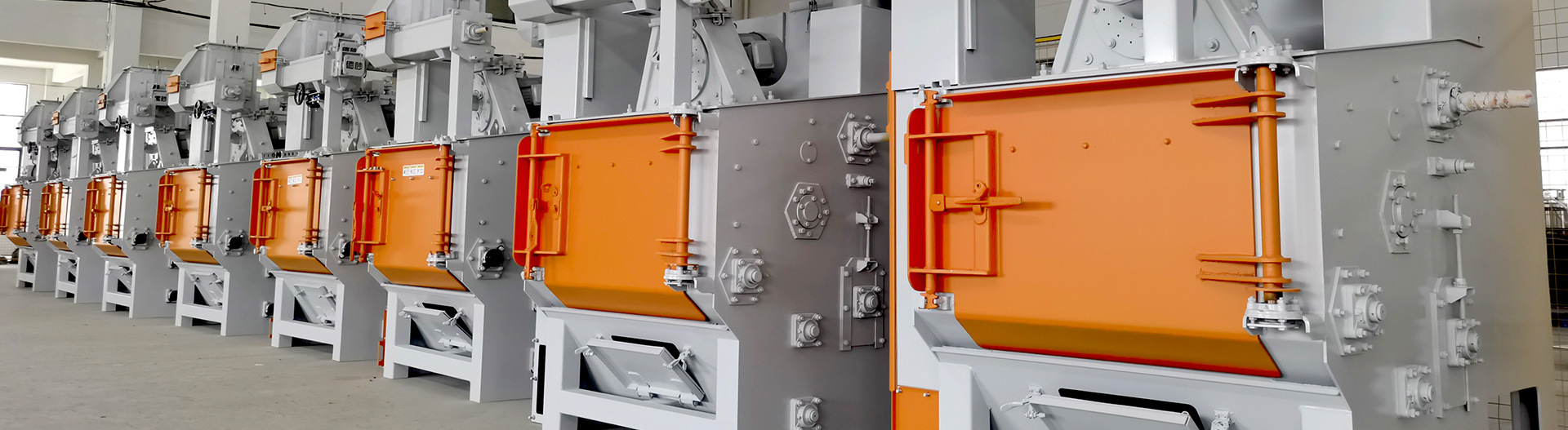
l This equipment adopts a straight-through suspension chain through-type shot blasting machine. It uses suspension chain to convey the workpieces and lifting fixtures to achieve mobile shot blasting. That is, the suspension chain conveys the workpieces through the shot blasting chamber. Once the workpieces are detected, shot blasting begins. The shot blasting machine forms a fan-shaped projectile beam with the high-speed thrown shot, which evenly strikes the surface of the workpieces, thereby achieving the cleaning purpose. After the shot blasting process is completed, manually check whether the dark corners of the product are cleaned up. For areas not covered by the shot blasting, manually re-spray.
l The designed production capacity of the equipment: 2m/min.
l Cleaning range: Diameter 800mm, height 2200mm
l Shot blasting station: straight-through type
l Cleanliness: Complies with GB8923.1-2011 Sa2.5
Technological process
Loading shot blasting cleaning automatic blowing Unloading
1.Loading
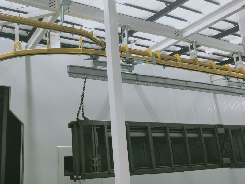
l At the feeding station, manual feeding is adopted. Each lifting gear is suspended in the predetermined way to hang the workpiece on the tooling.
l The self-rotation function of the equipment lifting gear at the loading station reduces the need for workers to rotate the tooling by hand during loading
l After the loading is completed, the workpieces are conveyed into the shot blasting station by the suspension chain hoist.
2.Shot blasting
l The workpiece enters the shot blasting station, the shot blasting machine is opened, and the shot blasting operation is carried out.
l Configure 12 sets of 11kw shot blasting machines, with 6 sets of shot blasting machines covering each side of the double-sided shot blasting.
l The lifting gear carrying the workpiece enters the shot blasting position to ensure that the surface of the workpiece is completely cleaned. The shot thrown out at high speed by the shot blasting machine forms a fan-shaped projectile beam, which strikes the surface of the workpiece with the ground, thereby achieving the purpose of cleaning.
1. Unloading
l After the shot blasting operation is completed, the workpieces are conveyed to the unloading area by the suspension chain for manual unloading and sand cleaning
Equipment processing capacity
l Coverage of sandblasting products:
It is used for surface cleaning of hydraulic support structural components and accessory products
l Cleaning range: The straight-through cleaning range has a diameter of 800mm and a height of 2200mm.
l Clean the material of the workpiece: iron
l Shot material: Steel shot
l Processing or Working Cycle Calculation Table:
Shot blasting time :2m/min
Precision requirement
l Shot blasting process requirements
v The cleanliness meets the standard of GB8923 A-B Sa2.5 grade, and the surface of the workpiece shows the original metallic color
v Shot blasting capacity: 200kg/min*11 sets
v Shot blasting machine motors: 11kw/ set *12 sets (with variable frequency speed regulation)
v The linear velocity of shot blasting is ≥77.5-96.54m/s
v The production cycle is 2 meters per minute
v Use steel shot with specifications ranging from φ0.8 to φ1.5 (cast steel shot, wire cut shot or ground shot)
Supply scope
1.Hanging chain through-type shot blasting machine :MCT-1022P11-12, 1 Set
1.1 Shot Blasting room 1set
1.2 Suspended chain conveyor system 1set
1.3 Screw feeding system 3sets
1.4 Hoist System 1set
1.5 Sorter system 1set
1.6 Shot flow control valve 12sets
1.7 Blast wheel system 12sets
1.8 Dry dust collector 1set
1.9 Maintenance Platform 1set
1.10 Electrical System 1set
1.11 Equipment User Manual (including Electronic Version) 1set
Equipment components and process descriptions
Introduction to MCT-1022P11-12 Suspension Chain Through-type Shot Blasting Machine
")
")
(1) All components of the entire equipment are cut by imported laser cutting machines and bent by CNC bending machines, effectively ensuring the precision of the products.
(2) The shell is welded with Q235, δ10mm steel plates.
(3) The entire shot blasting chamber is protected by rolled Mn13 high-wear-resistant steel plates with a thickness of no less than 10mm. The rolled Mn13 high-wear-resistant steel plates are fixed to the shell of the shot blasting chamber by integral welding. The service life of the entire protective plate in the shot blasting chamber is greater than 30,000 hours (pure operation time). The bottom of the chamber is equipped with a shot collection hopper. The upper part of the hopper is protected by rolled Mn13 high-wear-resistant plates with a thickness of no less than 16mm. The service life of the protective plates is all greater than 30,000 hours (pure operating time).
(4) The wear-resistant guard plate is fixed in reverse penetration, which increases the service life of the guard plate and reduces the later maintenance cost.
(5) At the bottom of the cleaning chamber, high manganese steel Mn13 is used for protection. The shot leakage groove is opened to ensure smooth shot reflux.
(6) Install anti-deviation limit switches at the inlet and outlet of the shot blasting room.
(7) Double-opening pneumatic doors are set at the front and back of the shot blasting cleaning room
(8) The working platform and guardrail set at the top of the chamber body;
(9) The position and layout of the shot blasting chamber and the shot blasting machine were all determined after computer three-dimensional dynamic shot blasting simulation.
(10) The hoist track groove is located at the top of the shot blasting chamber and adopts a patterned sealing design, with three layers of wear-resistant rubber sealing and a top brush sealing design to prevent steel shot from splashing on the top track groove. A sealing cover is set on the top track groove position to prevent steel shot from splashing
(11) Feeding and discharging gates:
A.The feeding and discharging of the shot blasting room adopt A curved-type anti-sand structure.
B. The suspension chain inlet and outlet mechanism of the shot blasting chamber adopts several layers of high-wear-resistant rubber for tight offset sealing, with high sealing performance, which can effectively ensure that the steel shot does not leak
(12) The exterior of the chamber is fixed with a frame, and inside the frame, sound-absorbing cotton is used to cover and partition plates for sound absorption treatment, reducing the noise generated by vibration and shot blasting of the chamber
2. Sealed chamber
")
The sealing chamber is divided into the feeding sealing chamber and the discharging sealing chamber
(1) The 3-meter section near the shot blasting chamber inside the sealing chamber and the transition chamber are all protected by rolled Mn13 wear-resistant steel plates with a thickness of no less than 8mm. The rest of the parts are all protected by 65Mn wear-resistant steel plates with a thickness of no less than 5mm. The guard plates are fixed to the chamber shell by welding, and the service life of the guard plates is more than 30,000 hours.
(2) At the bottom of the sealed chamber and the transition chamber, there are shot collection hoppers. All the hoppers are equipped with perforated screen plates to screen the shot. Qualified shot falls into the hoppers for recycling. Large pieces of material fall on the screen plates and are cleaned manually at regular intervals. On the perforated screen plates 3 meters away from the shot blasting chamber, Mn13 wear-resistant steel plates with a thickness of no less than 12mm are laid to protect the hoppers.
(3) Four network-type explosion-proof cameras and the corresponding display equipment are installed in the sealed room. The camera Windows are automatically protected by pneumatic wear-resistant plug plates.
(4) The opening of the walking balance beam at the top of the chamber is equipped with a sealing device, all of which adopt a labyrinth sealing structure. The top sealing device of the chamber body is composed of rolled Mn13 wear-resistant steel plates with a thickness of no less than 12mm, three layers of polyurethane plates, nylon wool pads, etc., to prevent the rebound of bullets to the outside of the chamber. The service life of the protective plate is greater than 30,000 hours, and the service life of other flexible sealing parts is greater than 10,000 hours.
(5) The outdoor end of the supplementary spray cleaning is equipped with pneumatic double doors. Both doors are suspended. The door body is a welded structure of steel plates with a thickness of no less than 4mm and square steel pipes. The inner side of the door is protected by 65Mn wear-resistant steel plates with a thickness of no less than 6mm, and the service life is more than 30,000 hours. Under each gate, there is a pill return trough to prevent the accumulation of pills in the guide trough of the gate.
3. Hoist
")
(1) The enhanced capacity is ≥140T/h;
(2) The lifting belt adopts a wear-resistant and high-strength belt.
(3) The hoist is equipped with photoelectric speed detection to prevent the belt from slipping and causing power damage.
(4) A detachable movable guard plate is installed opposite the sand discharge port of the hopper on the top of the elevator to prevent the outer shell of the separator from being punctured.
(5) The hoist is precisely welded from steel plates and can be disassembled in sections. There are maintenance and inspection Windows, which are easy to repair.
(6) A drive reduction motor is located at the top of the hoist and serves as the power source for lifting shot materials.
(7) The system includes: The bucket elevator is composed of a cycloidal pinwheel reducer, one precisely machined wheel hub each at the top and bottom, one set of high-performance wear-resistant belts, several buckets, a closed cover shell and a tensioning device, etc.
(8) A cycloidal pinwheel reducer of 11 kw is adopted
4. Air-washed separator and shot storage box
")
(1) Separation capacity: ≥140T/H; The air screen is separated, and the inflow of steel shot is continuously maintained in a thin band, equipped with an air conditioning valve.
(2) The shot storage box is located at the lower part of the air-washing type separator. With an observation window;
(3) 5.5kw cycloidal pinwheel reducer is adopted;
(4) This machine adopts the most advanced full-screen curtain flow type shot and slag separator in the world at present, and the dust content of the separated steel shot is less than 6%.
(5) Working Principle: The shot and sand mixture flowing in from the bucket elevator is pushed by the conveying screw, causing it to be evenly distributed along the entire length of the separator. Finally, it reaches the overflow outlet at the end of the separator, where material starts to overflow. The material level sensor senses the material flow, forming a waterfall-like shot and sand flow curtain along the length of the separator. Under the full curtain state, by using the principle of gravity air separation, the shot in the flow curtain is effectively separated from the metal oxide scale fragments, broken shot and dust. The large particle waste is blocked by the screen, while the fine shot and dust flow out from the waste outlet. The shot enters the shot silo for circulation.
(6) Welded structure, with multiple elaborately designed compartments inside for wind direction guidance. The front is an openable inspection door, which is used for daily observation. The door is equipped with an air inlet for inspection and maintenance, providing an air medium for dust separation.
(7) The following is connected to the silo. The qualified shot materials after sorting flow through the silo for storage, ready for reuse.e.
5. Spiral conveying system
")
(1)The longitudinal and transverse screw conveying capacity is ≥140T/h;
(2)The spiral shaft is welded to the 45# steel shaft head with seamless steel pipe and processed as a whole after welding. The helical blades are made of 16Mn. Both its inner and outer circles are processed by special techniques nd then stretched. The pitch and outer circle dimensions are very precise, which increases the service life.
(3)The screw conveyor is composed of cycloidal pinwheel reducer, screw shaft, conveying cover, bearing with seat, etc. It is an important component of the shot circulation system of the shot blasting machine.
(4)Adopt
a 5.5kw cycloidal pinwheel reducer;
6.FS6.0 Blast Wheel
")
(1) The shell of the shot blasting machine is cut by an imported laser cutting machine and bent by a CNC bending machine, effectively ensuring the precision of the product.
(2) The motor is belt-driven (labyrinth type to prevent steel shot and dust from entering), the output shaft is thickened, and SKF bearings are used, with a power of 11kw.
(3) The impeller has undergone dynamic balance tests and generates minimal vibration when rotating at high speed.
(4) The blades, shot distribution wheels, directional sleeves, side guard plates and top plates are made by machining and heat treatment. The accessories have high precision and a long service life. The weight difference of the blades is within 2g. The vibration is extremely small when rotating at high speed. The end guard plates are made of Mn13 material.
(5) The shot ejection velocity is 77.5 to 86.54m/s, and the speed range of the frequency converter is 1500 to 3200 revolutions per minute
(6) The shot flow rate is 200kg/min per unit
(7) The service life of the blades, shot distribution wheel, directional sleeve, top guard plate, side guard plate and impeller is 1000 hours. The service life of the end guard plate is 2000 hours.
(8) A rubber sheet is used to separate the shot blasting inlet pipe from the directional sleeve to reduce the noise caused by friction.
(9) Install sound-absorbing covers on the outside of each group of shot blasting.
7. Steel Shot Control Valve
")
(1) It is a closed steel structure with inspection ports. The opening and closing of the valve are electronically and pneumatically controlled. The flow rate of steel shot is controlled by manually adjusted positioning bolts.
(2) Air consumption: 0.2-0.6 m³/min, air pressure: 0.5-0.7Mpa
(3) 12 sets of shot flow control valves. Fully sealed structural design with lockable inspection openings and equipped with two bearings.
(4) The opening and closing of this device is pneumatically controlled by a cylinder. The flow rate of the shot is pushed by the cylinder to open the valve core, and then controlled by the limit of the guide column. The flow rate of the shot can be displayed on the display screen on the electrical control cabinet.
(5) At the upper end of each flow valve, there is a manual stop valve. If the flow valve needs to be repaired, it can be closed to stop the shot flowing down from the silo, facilitating maintenance.
8..Maintenance Platform
(1) The top of the room is equipped with a working platform and guardrails, as well as a straight ladder and guardrails, which facilitate maintenance and repair.
(2) The platform and guardrails are made of steel structure.
")
9. Pre-separator for Sedimentation Chamber
(1)A sedimentation chamber pre-separator is added in front of the cyclone dust collector to filter out the small stainless steel shot and introduce it into the shot blasting chamber.
(2) The dust on its upper part is sucked into the cyclone dust collector for dust filtration
")
10. Cartridge Dust Collector
")
(1) The cartridge dust collector is a key component in the dust removal process of the sandblasting room. Its working condition directly affects the indoor environment and outdoor emission standards. This dust collector adopts the internationally popular Torritt submersible dust collector structure. The filter element arrangement structure is reasonably laid out, installed in a horizontal combination, and features top air intake, bottom air exhaust, and high-pressure pulse pneumatic reverse blowing for dust cleaning, achieving an excellent effect. This structure is conducive to the introduction of dusty gas into each filter cartridge carrier in the dust collector chamber for uniform distribution. It is also beneficial for the dust that is instantly bounced off during reverse blowing and cleaning to fall, reducing the possibility of secondary adsorption. The bottom exhaust structure directly introduces the air into the fan through the clean air chamber. The fan motor is floor-standing, which enhances the stability of the equipment and saves unnecessary waste caused by pipeline connections. This dust collector's dust collection hopper is equipped with a star-shaped electric ash discharge valve and a dust collection device. After regular ash cleaning, it is pulled to the designated position for dust treatment, eliminating the need for secondary flying and environmental pollution caused by transportation in other containers.
(2) This dust collector features good air permeability, low resistance, low energy consumption and reliable filtration performance. The overall design structure of the dust collector is elegant, refined and stable. The assembly of the filter cartridges adopts a high-speed connection method, and at the same time, the disassembly and assembly of the filter cartridges are very convenient, reducing the physical labor intensity of workers and improving working conditions.
(3) The air inlet of the dust collector is equipped with a damper. The air volume can be adjusted according to the usage of the equipment
(4) It is equipped with an automatic back-blowing cleaning device and the back-blowing time interval can be set
(5) The air inlet of the dust collector is equipped with a damper. The air volume can be adjusted according to the usage of the equipment
(6) Dust collector parameters:
l Dust removal ventilation volume: 50,000 m³/h
l Power: 45Kw
l Pulse dust removal
l The dust removal efficiency is 99.8%
l The dust emission concentration is ≤20mg/m³
l The air consumption is 1.2-1.5m³/min, the air pressure is 0.5-0.7Mpa, and the total pressure is 1882pa.
11. Electrical control cabinet
(1) Main power supply three-phase AC: 380V± 10%, 50Hz±2
(2) Control voltage: DC24V
(3) Lighting fixtures are installed inside the control cabinet. The lights turn on when the door is open and off when the door is closed
(4) Equipped with a storage area for equipment and materials
(5) The panel is equipped with a button for checking if the indicator light is working properly, so that it can be inspected at any time
(6) At the bottom, there is a three-color indicator light: when the red light flashes, it indicates a fault state; when the yellow light flashes, it indicates a maintenance state; when the green light flashes, it indicates a manual state; and the green continuous light indicates that the equipment is in a normal working state. Audible and visual alarms can be achieved
(7) Color touch screen for controlling the entire device. The switchable pages are as follows:
l System A monitoring - Monitor the operational status of each system of the entire equipment
l Parameter Settings - Used to set the shot blasting process parameters
l Manual adjustment - used for manual control of various systems during maintenance
l Maintenance Tips - Regularly remind users to maintain each system of the device
l Alarm Information - Alarm Information Recording
12. Electrical System
(1) The entire line is controlled by PLC, featuring two working modes: manual and automatic
(2) This system is mainly composed of low-voltage electrical components, programmable controllers (Siemens PLC), etc
(3) It is equipped with a fault alarm function for the shot circulation system. If any component of this system malfunctions, the components on it will automatically stop running to prevent the shot from getting stuck and burning out the power unit
(4) Each piece of equipment is controlled by PLC to operate according to the program, achieving automatic shot blasting operation:
l At the front end of the shot blasting station, there is A workpiece detection system designed. Through the displacement counting and interlocking control of the PLC, the opening and closing times of the shot blasting machine and the shot supply gate valve, as well as the opening quantity of the shot blasting machine and the shot supply gate, can be achieved. This avoids the empty shot blasting phenomenon of the shot blasting machine and greatly improves the utilization rate of the shot.
l The shot conveying system is equipped with a fault alarm function for the shot circulation system. If any component of this system malfunctions, the system will immediately alarm and shut down, and the components above it will automatically stop running to prevent the shot from getting stuck and burning out the power device.
l All cables and air pipes are installed with model cable trays and sealed. All cables, cable trays and air pipes are neatly, standardly and reasonably installed, and all are clearly marked, which is convenient for fault repair and location
l All grounding wires comply with national standards
l The electrical control cabinet adopts a closed cabinet structure, with a profiled frame and a surface coated with plastic spraying. It is also easy to install in parallel cabinets.
l Functional requirements for the electrical control cabinet: Control of all drivers from the control panel, complete display of operating status, alarm and status output, main Settings with password protection, clear status display when setting parameters, and compliance with national standards.
Main Technology Data
NO. | Item | Name | Technology Data | ||
1 | Shot blast chamber | Main chamber | Main chamber material | Q235, T:10mm | |
Protective board material | Mn13,T:10mm | ||||
Door of input and output | Double-cylinder automatic door | ||||
2 | Blast wheel | Blast wheel | Model | Q11 | |
QTY | 12 Set | ||||
Motor Power | 11Kw/set*12sets | ||||
Shot blasting quantity | 200kg/min*12sets | ||||
Blade QTY. | 8 pcs/set | ||||
3 | Steel shot circulation system | Steel shot control valve | QTY. | 12 sets | |
Spiral pusher | QTY. | 3sets | |||
Motor power of the roller screen screw pusher | 5.5Kw*1set | ||||
The power of the bottom spiral push motor | 3Kw*2 sets | ||||
Separator | QTY | 1set | |||
Separation method | Screen separation + wind separation system | ||||
Hoist | QTY | 1 set | |||
Lift quantity | 140T/H | ||||
Motor power | 11KW/set | ||||
4
| Electrical control system | Control cabinet type | Rittal | ||
PLC | Siemens | ||||
Human-machine interface | 10-inch touch screen | ||||
Electrical control cabinet air conditioner | 1 set | ||||
5 | Dust removal system | Cartridge dust collector | Model | DC48 | |
QTY. | 1 Set | ||||
Fan power | 45Kw | ||||
Air volume | 50000m3/h | ||||
Dust emission | ≤20mg/m3 | ||||
6. | Equipment appearance | Surface paint color | Standard color or provided by the customer | ||
7 | The power of the equipment is slightly adjusted according to the final design | ||||
Machine Running Requirement
NO. | Item | Running Requirement | |
1 | Gas source | Gas supply pressure | 5-7bar. No water and no oil |
2 | Power supply | Power supply | 380V± 10%, 3 phases, 50HZ±2 |
Total power | kw | ||
3 | Workshop working environment | Temperature | 0℃-45℃ |
Relative humidity | ≤99% | ||
4 | Abrasive | Steel grit | 0.6-1.0mm |
The initial filling amount of steel grit | About 20T | ||
Main parts brand
NO | Name | Brand |
1 | Fan | China brand |
2 | Button/Indicator light | Chint |
3 | Button switch | Chint |
4 | Contactor | Chint |
5 | Motor circuit breaker | Chint |
6 | Relay | Chint |
7 | PLC | Siemens |
8 | Touch screen | Siemens |
9 | Pneumatic control valve | Yadek |
10 | Electrical control cabinet | Rittal |
11 | Electrical control cabinet air conditioner | Special for electrical cabinets |
12 | Blast wheel motor | China brand |
13 | Deceleration motor | China brand |
Spare Parts List
No | Name | Use Life | Model |
1 | Blade | ≥1500h | Q11 |
2 | Steel shot divider | ≥2000h | Q11 |
3 | Directional sleeve | ≥2000h | Q11 |
4 | Top guard plate | ≥2000h | Q11 |
5 | Side guard plate | ≥2000h | Q11 |
6 | End guard plate | ≥2500h | Q11 |
7 | Wheel | ≥3000h | Q11 |
sign up newsletter
Email:cennia@szmizhi.com
Add::104,Building 27,Third Industrial Zone, Longxi Community,Longgang District,Shenzhen,China.